


| Quantity: | |
|---|---|
An irregular shape is rarely the hard part of a vacuum formed liner. What stops a project is release. A deep pocket with a narrow mouth, an undercut boss, or a sudden change of section can grip a part so tightly that operators pry it out, and it can grip the mould the same way. We plan the liner around a release direction before we draw a single cavity.
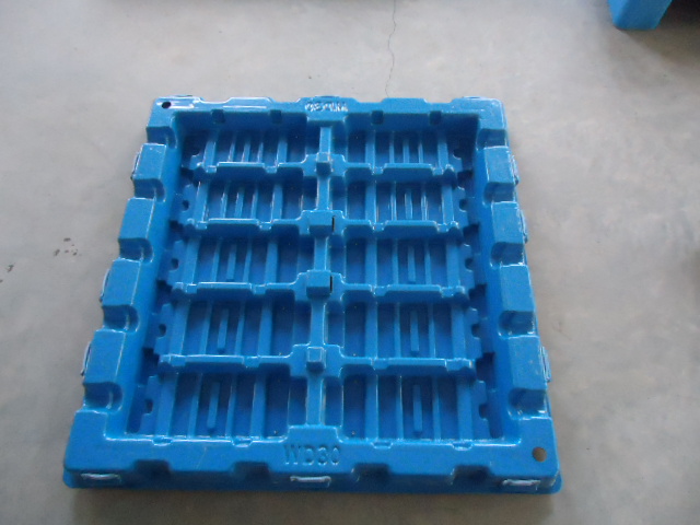
Release direction comes from the part. The main axis follows the easiest lift out of the crate, the component rests on its agreed support faces, and every cavity mouth faces that direction. Features that point sideways are either redrawn as a relief slot, allowed a small local draft, or assigned to a second half of the liner. The drawing states the direction so packing and moulding agree.
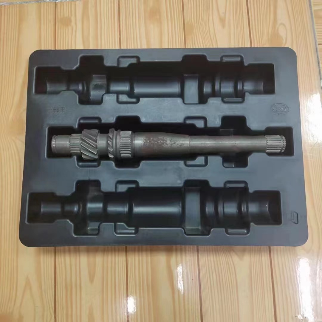
Deep cavities and true undercuts are split rather than forced. Two formed halves close over the part like a loose mould, flanges located by moulded steps; a soft hinge keeps the pair together. Very deep parts release in sections, each half lifting its share. A boss or pipe that must pass through gets a relief slot instead of a full pocket.
Splitting changes the forming problem too. Each half needs its own workable draw and even wall thickness, and the joint face is placed where it never touches the part or takes a stacking load. Narrow mouths that would web badly in one piece become shallow, open forms when divided. The pair is trimmed so the flanges meet cleanly with no raised burr at the seam.
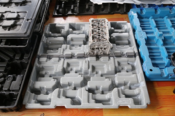
Daily use decides the details. Closing order is obvious from the shape, or it is marked: a colour band on the left half, a plain right half, so the pair cannot be swapped between part families. Hinges are checked each return, relief slots stay free of swarf and dust, and a warped half is replaced alone instead of retiring the whole set.
Verification uses the real motion. Operators lift each part out and set it back at line speed; the trial records whether any feature snagged and whether the halves seated without forcing. Packs then run vibration and a drop, and the joint face is inspected for wear. A seam that starts to pinch the part is corrected in the tool, not padded in the crate.
To quote, send the 3D data of the irregular parts, their weights and support faces, quantity per box, crate inner dimensions, stacked layers, cleaning agents, temperature range, target cycles, and annual volume. We return a release direction drawing, a split layout with joint faces and hinges, formed samples, and the take out and refit records from a line trial.


